Amplifier models:
There exist four amplifier models;
- Voltage Amplifier Model
- Current Amplifier Model
- Transconductance Amplifier Model
- Transresistance Amplifier Model
 |
| Simplified amplifier model |
To begin, we need to understand the voltage amplifier model.
Voltage amplifier model
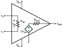
Consider the image above. In the case of the voltage amplifier model, the internal components can be modelled as the following;
Where
Vi = input voltage
Vo = output voltage
Ii = input current
Io = output current
Ri = input resistance/impedance
Ro = output resistance/impedance
The gain property of this model is represented by a
voltage-controlled voltage source.
(More information on which can be found
here)
Note:
By definition, voltage gain, Av = Vo/Vi
Open-circuit voltage gain = Avo
(if the load is an open circuit, as shown above, there is no drop across the output resistance, and Vo = Avo*Vi)
Given a model with external loading (i.e. with external components attached), the model can be simplified as follows, for analysis.

Aside from voltage gain. there also exists current gain, Ai, which can be calculated as follows;
Ai = Io/Ii = (Vo/Rl)/(Vi/Ri) = Av*(Ri/Rl)
Current amplifier model
Another method of modelling the amplifier is the current amplifier model.
This can be modelled as the following;
The gain property of this model is represented by a current-controlled current source.
Note:
By definition, current gain Ai = Io/Ii
Open-circuit current gain = Aisc
(If the load is a short circuit, no current flows through resistor Ro, and Io/Ii is short-circuit current gain.)
Transconductance amplifier model
Another method of modelling the amplifier is the transconductance-amplifier model.
This can be modelled as the following;
The gain property of this model is represented by a voltage-controlled current source.
Observe that while the transconductance-amplifier and current-amplifier models use the Norton equivalent circuit, the voltage-amplifier model uses the Theverin equivalent circuit, as will the transresistance model, as will be demonstrated below.
Transresistance amplifier model
Another method of modelling the amplifier is the transresistance-amplifier model.
This can be modelled as the following;
The gain property of this model is represented by a current-controlled voltage source.
On cascading amplifiers:
Ideal amplifiers
(To reduce loading effects)
If the reasons for the above table remain unknown, consider the following
Inputs:
The
voltage and
transconductance models are voltage controlled.
Thus, the input impedance Ri is ideally large, this maximises the voltage drop Vi to be maximised over Ri. (See earlier diagrams)
The
current and
transresistance models are current controlled.
Thus, to maximise the input current Ii, Ri is minimised.
Outputs:
The
voltage and
transresistance models are voltage sources.
Thus, to maximise the output Vo, the output impedance Ro is minimised. By doing so, the voltage drop over Rl is maximised.
The
current and
transconductance models are current sources.
Thus, to maximise the output current Io, the output impedance Ro is maximised, allowing the current to flow out of the amplifier (Ro becomes akin to an open circuit).
(Note that this logic holds because for the voltage sources, a Theverin equivalent circuit is used, while for the current sources, a Norton equivalent circuit is used. More information on Theverin and Norton can be found
here.)
Hopefully, this provides an introduction to amplifier models. If you feel that any part of this post needs improvements, feel free to contact us at engyfun@gmail.com
References:
Kroll, (2009). 1st ed. [ebook] Available at: http://surf.hep.upenn.edu/~kroll/p364_fall09/handouts/simple_voltage_amplifier.pdf [Accessed 5 Mar. 2015].
Lu, T. (2015). Electronics IIM 2015. Adelaide: University of Adelaide.


.JPG)
.JPG)